Dear all,
Today we are going to explore the Library Parts creation in ARCHICAD. There are several library parts we can create without necessity of coding in GDL or do anything complicated. Customised library parts is incredibly useful.
The example we are going to use is the creation of a Curtain Wall Frame and a Curtain Wall Cap. I am going to import a detail drawing of a manufacturer catalog in PDF and I am going to build my CW Frame and Cap out of it. The manufacturer’s detail I am going to use in this case is called “Wausau”. I just found it googling and I think is fair to give them credits since I am going to use their product for this article.
So let’s get to it!
1. Import the CW detail in PDF
The first thing is to drag the PDF document into the AC floor plan window. The PDF will appear as a Drawing and we will be asked to select which page we want to import.

Then we right click on the Drawing that contains the PDF and select explode. We have several options when doing this action but basically it will convert all the 2D elements in the PDF in Lines, Polylines and Fills.
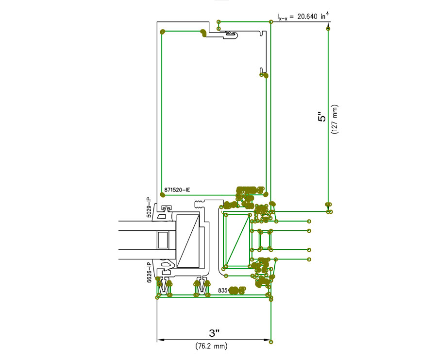
If you do not need all the graphic information on the page of the PDF you can modify the window of the drawing selection the edge or any of the active points. In this case I had to scale the drawing because it was bigger than the real dimensions. I just followed the dimensions on the detail.
Of course this first step can be done importing a DWG file from the manufacturer.
2. Convert it into 3D geometry
Once we have our 2D group of elements what I did is with the Magic Wand I created a slab inside the part of the detail that is meant to be solid. I am going to use it as a frame and a cap for my CW profile. Let’s have a look in 3D to see how it looks like..

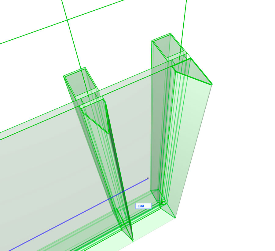
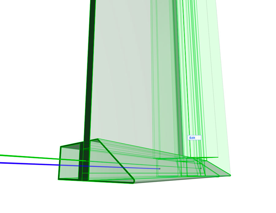
Once we have a slab in 3D with the shape of the solid elements in our profile we need to be sure it is located in the right way in the 3D in order to save it as a CW frame and cap. The lowest part of the Slab needs to be located in the “0,00 level” of our model. It means that the slab has to be seated on the “0,00” elevation of our model. If is higher or lower it will give problems eventually. It doesn’t matter how thick or tall is our slab, just be sure it sits in the “0” level of our model.

Another important note is that the Slab that will be saved as our CW frame or Cap needs to be orientated vertically. Also it needs to be “looking up”. What it means is that the cap, which is the exterior part of the CW should be above the Frame that is usually located in the interior of the enclosed space by the CW. It sounds complicated but use the image as a reference to test it..
We can use several slabs of different Building Materials to create a CW frame. That depends in how much detail we want to add to our CW.

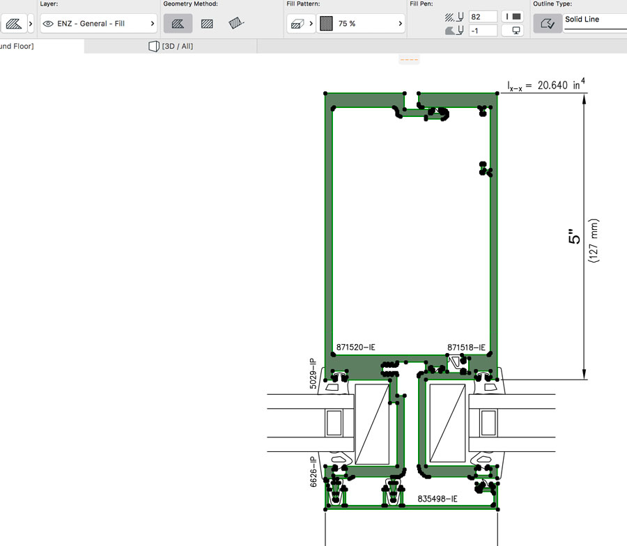
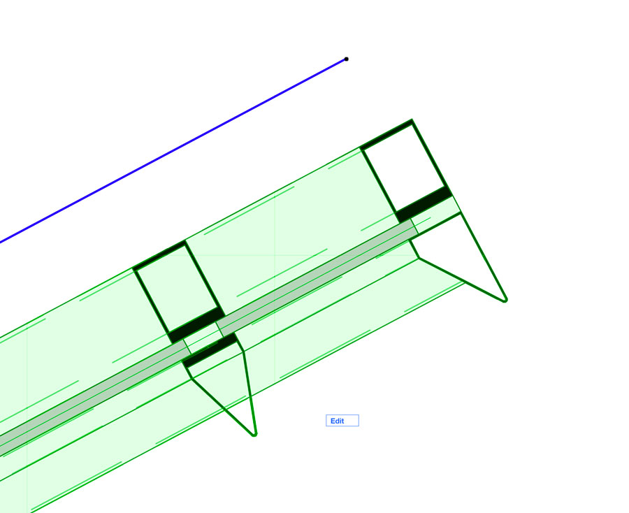
Once I converted my profile in a 3D geometry (slab) what I did is to duplicate and simplify my geometry as you can see in the image. There are two reasons to do this:
The first one is because the profile I created for my CW frame and Cap is very detailed and will make my model very heavy. I would’t personally input that much amount of geometry in my CW because the moment you start modelling several and large CWs the model will be very very heavy.
In this way I have a profile compose by a Frame and Cap with the correct dimensions of the manufacturer’s catalogue with slightly more detail than the CW profiles used to have. Quite useful already even for a scale 1:50.
The second reason I will tell you at the end of the article..
3. Save the CW Frame and Cap separately
We need to save the Frame and the Cap separately. A part of what we just modelled will be the Frame and the other part will be the Cap. To be precise the Cap is everything that is outside the exterior face of the panel of the CW and the Frame is everything that is inside the interior face of the panel.
So we need to save as the “Cap” everything that will be located in the “outside” part of the Panel of the CW and we need to save as a “Frame” everything form the profile that will be in the “inside” part. Is it clear? I hope that by looking to the images it is.
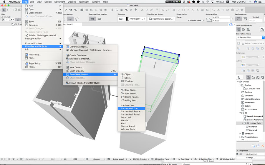
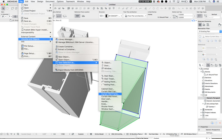
We just need to select in the 3D window or in the floor plan and go to File > Libraries and Objects > Save selection as and chose from the menu “Curtain Wall Frame” or “Curtain Wall Cap” as shown in the image. We give a name to our CW Frame and then we will do the same with the CW Cap saving it with a name as well.
So any of our CW profiles which can be Mullion, Transom or Boundary is going to be composed by these 2 elements, Frame and Cap.
4. Apply it to a CW in our model
Now we need to go into the settings of our CW. We go into the Mullion section and first we select in the tap of “Frame type and geometry” the option that says “Modular Frame 21” (in the case of AC21).

Below this tab in the Curtain Wall Frame Settings we move to the menu “General Settings”. Here we select in “Frame Type” the option that says “Custom Frame”. And in the Custom Frame name list we select the Frame we saved previously.
If we go to the 3D window and use a Cutting Plane to cut the CW we will see the look of our new Mullion..

Regarding the 2D representation in order to see correctly the Frame and Cap we just design, what we need to do is to choose the option “Projected with Overhead” in the “Floor Plan Display” tab inside the Floor Plan and Section Settings of the CW.


5. The Gap
As I told you before there was another reason why I simplify the CW profile. This feature of AC allow us to create a Frame and Cap for our CW. We can also create a Panel and I will explain this in a coming post. But we cannot create anything that is part of the profile that will occupy the area of the CW panel. I know it sounds complicated but is simple. Just check the next images.

This is exactly the Frame and the Cap I created at the beginning based on the detail drawing of the manufacturer. I applied it to my Curtain Wall. Don’t you notice something weird? It is not totally the same as what I wanted it to be. It looks actually quite good overall but is not a exactly the representation I wanted.
We can see that the part of the metal Mullion that goes through the glass panel disappears. I haven’t found a way to make my saved Frame or Cap to go through the panel area of the CW. This is why I mentioned before that “the frame goes from the interior face of the panel towards the inside and the cap goes from the exterior face of the panel towards the outside. But in between them it is empty.
So “the Gap” I found in this workflow is that I cannot make my Mullion to be completed from the Frame till the Cap. If any of the readers has found the way to do it please share it with me… I am always willing to learn.

6. Conclusion
The first time I wanted to customise my CW profiles I just intended to add detail as the construction detail I used for this example. I realised about the gap I mentioned before and since then I haven’t managed to fix it. But then I found this workflow extremely useful to customise CW profiles and parts in order to make them look according to my design..
The level of detail of the simplified option I used in this example is enough to produce all documentation we may need till a 1:50 scale. It is not very smart to add too much detail to a CW before we need to get into 1:20 or 1:5 details. And for that case I would personally start using details from the catalogs of the manufacturers and insert or refer them into my own construction drawings.
Having a Parametric tool such as the CW that automatically displays enough detail to be used even till a 1:50 scale is very reliable and saves already a lot of time. Trying to add too much detail I realised it became so heavy to edit that I rather stop trying to add the complete detail to the profile. What I have shown in this exercise is useful enough for me and keeps the model manageable.
All the information you may need to add to a CW Mullion, Transom or Boundary is possible to be added any way in the Classification and Properties (the old Categories and Properties) of those components.
I know this exercise is a bit tricky but if you test it and you find problems just write us a comment and we will explain further.
But as you can see in these images it is quite useful to be able to customise the design of the profiles of a CW. As I always say the BIM workflow starts at the Design Stage, so if I design or customise the CW for my projects I also can do it in my BIM model. This is what we just did in this exercise, use a real detail to design and adapt our BIM component.
I hope you found this article useful.
Thank you for reading us!

Library Parts 1: Curtain Wall Frame & Caps
Get our latest posts and projects delivered directly to your inbox!
Processing…
Success! You're on the list.
Whoops! There was an error and we couldn't process your subscription. Please reload the page and try again.